> For the complete documentation index, see [llms.txt](https://auvidea.gitbook.io/x221-lc-ai/llms.txt). Markdown versions of documentation pages are available by appending `.md` to page URLs; this page is available as [Markdown](https://auvidea.gitbook.io/x221-lc-ai/manual/x221-overview.md).

# X221 Overview

<figure><img src="https://22655135-files.gitbook.io/~/files/v0/b/gitbook-x-prod.appspot.com/o/spaces%2FcUvqgsEqIqoso9khJDrs%2Fuploads%2F5fDeh5JVxKqizsP8X4U3%2F5.png?alt=media" alt=""><figcaption></figcaption></figure>

## Product SKU

<table><thead><tr><th width="173">SKU</th><th>Description</th></tr></thead><tbody><tr><td>70415</td><td>Standard version</td></tr><tr><td>70415-AI</td><td>All in (AI)</td></tr><tr><td>70415-AI-1LM</td><td>All in (AI), 1x LM823 (1LM)</td></tr><tr><td>70415-AI-2LM</td><td>All in (AI), 2x LM823 (2LM)</td></tr></tbody></table>

## Document versions and changes

<table><thead><tr><th width="133">Version</th><th>Changes</th></tr></thead><tbody><tr><td>1.0</td><td>Initial document, internal verification process</td></tr><tr><td>1.1</td><td>Internal verification process</td></tr><tr><td>1.2</td><td>Restructuring of document, added Appendix B, C</td></tr><tr><td>1.3</td><td>Adding Socket Pins</td></tr><tr><td>1.4</td><td>Adding Appendix D &#x26; E and fixed missing table in Appendix B</td></tr><tr><td>1.5</td><td>Minor changes</td></tr><tr><td>1.6</td><td>Updated Appendix D, added pinout description header</td></tr><tr><td>1.7</td><td>Corrected the Extension port for CSI-2 from up to 8 cameras to up to 4 cameras</td></tr><tr><td>1.8</td><td>Ported Manual to Gitbook, added Bootprolem information</td></tr></tbody></table>

{% hint style="warning" %}
Auvidea can take no responsibility for the accuracy or completeness of any information presented in an exported PDF document as the export feature is developed, managed and maintained by GitBook. Those export mechanisms are subject to change without interaction by Auvidea. Please note that Auvidea includes this version table to identify the document and reference changes.
{% endhint %}

## Product revisions and changes

<table><thead><tr><th width="143">Version</th><th>Changes</th></tr></thead><tbody><tr><td>38413-2</td><td>Added Crypto chip</td></tr><tr><td>38413-3</td><td><mark style="color:red;">xxx</mark></td></tr><tr><td>38413-4</td><td>Safety MCU, Change of Ethernet controllers, MCU UART to LTE, CAN RX/TX</td></tr><tr><td>38413-5</td><td><mark style="color:red;">xxx</mark></td></tr><tr><td>38413-6</td><td><mark style="color:red;">xxx</mark></td></tr></tbody></table>

{% hint style="warning" %}

### Bootproblem <a href="#toc126743645" id="toc126743645"></a>

**Some of the X221 has got a boot problem:**

Affected carrier boards:

* X221 – 38413 rev 5 and below
* X221-AI – 38413 rev 5 and below (MCU firmware fix available)
  {% endhint %}

### **What is the boot problem**

The Jetson's boot process could randomly get interrupted due to falsely receiving a signal through the UART interface.

### How is it caused

The UART's receive pin (pin 3 = UART3\_RX) is floating due to a missing pull down resistor. This can cause the signal to oscillate right around the threshold of the level shifter. This then turns this false signal into a proper 3.3V signal that send a false "keystroke" to the Jetson. If the Jetson is in the bootloader part of the boot process and at that particular time happens to wait for an input during: "Hit any key to stop autoboot" then the Jetson enters the U-Boot/CBoot/UEFI and stops the boot process. This interrupt message accepts any signal and has a three-second time window.

### Observations of our limited testing (your mileage may vary)

#### Nothing plugged into the UART connector

Most of the time the issue did not appear, however other surrounding signals could interfere and have an impact on this behavior, same with the aging of the carrier board and degradation of the components.

#### UART is connected to another device

The problem should not appear since the signal is not floating anymore and the message interrupting the boot process would have to come from the other device instead.

#### UART has wires plugged in which are not connected to anything

In this case, problems may arise. If the distance is too small to the carrier board, a person can trigger signals at the Jetson through electromagnetic waves.\
This can be thought of as a kind of antenna, which then receives signals.\
For example, simply approaching a 15cm/\~6in long "antenna" with your hand at a distance of \~20cm/\~8in or less causes the Jetson so stop booting 100% of the time.

### How to fix this issue

The ideal solution is to add the missing resistor in the schematics, but this requires a new hardware revision. On some of the above-mentioned versions of the affected carrier boards, this issue can be resolved by using a special MCU firmware which adds an internal pull down resistance to keep the signal from floating. For the other boards, the temporary fix is to connect UART RX to ground, so the signal gets pulled down. The connector that shorts these two pins (pin 3 and pin 6) will be included.

## Model comparison <a href="#toc105600611" id="toc105600611"></a>

<table data-full-width="true"><thead><tr><th width="347">Description</th><th width="165">X221-LC r2</th><th width="168">X221-AI r2</th><th width="165">X221 r4</th><th>X221-AI r4</th></tr></thead><tbody><tr><td>2x GbE (RJ45)</td><td>1x native, 1x i210 PCIe to GbE</td><td>1x native, 1x i210 PCIe to GbE</td><td>2x RTL8111 PCIe to GbE</td><td>2x RTL8111 PCIe to GbE</td></tr><tr><td>HDMI out</td><td>1x</td><td>1x</td><td>1x</td><td>1x</td></tr><tr><td>USB 2.0</td><td>1x micro</td><td>4x</td><td>1x micro</td><td>4x</td></tr><tr><td>USB 3.0</td><td>2x</td><td>2x</td><td>2x</td><td>2x</td></tr><tr><td>LM823 Wifi</td><td>-</td><td>2x (optional)</td><td>-</td><td>2x (optional)</td></tr><tr><td>Safety MCU (for JAXi)</td><td>-</td><td>-</td><td>-</td><td>yes</td></tr><tr><td>Basic MCU</td><td>yes</td><td>yes</td><td>yes</td><td>-</td></tr><tr><td>Remote power control &#x26; debug via LTE</td><td>-</td><td>-</td><td>-</td><td>yes</td></tr><tr><td>MicroSD/UFS card slot</td><td>-</td><td>1x</td><td>-</td><td>1x</td></tr><tr><td>UART</td><td>1x</td><td>2x</td><td>1x</td><td>3x</td></tr><tr><td>I2S</td><td>-</td><td>2x</td><td>-</td><td>2x</td></tr><tr><td>I2C</td><td>1x</td><td>2x</td><td>1x</td><td>2x</td></tr><tr><td>Extension port for PCIe x4/x1/USB/UART/I2C/GPIO</td><td>-</td><td>yes</td><td>-</td><td>yes</td></tr><tr><td>Extension port for CSI-2</td><td>-</td><td>3x4X or 4x4X (with addon board M222 (38548) or M220 (38451))</td><td>-</td><td>3x4X or 4x4X<br>(with addon board M222 (38548) or M220 (38451))</td></tr><tr><td>Operating Voltage</td><td>12V</td><td>12-48V</td><td>12V</td><td>12-48V</td></tr><tr><td>Jetson power modes</td><td>30W + MAXN</td><td>30W</td><td>30W + MAXN</td><td>30W</td></tr><tr><td>Super Cap UPS</td><td>-</td><td>(optional)</td><td>-</td><td>(optional)</td></tr><tr><td>Power out (5V, 12V)</td><td>-</td><td>yes</td><td>-</td><td>yes</td></tr><tr><td>Power/Reset/Force-Recovery Buttons</td><td>-</td><td>yes</td><td>-</td><td>yes</td></tr><tr><td>RTC super cap</td><td>200mF</td><td>200mF</td><td>200mF</td><td>200mF</td></tr><tr><td>Auto flashing</td><td>yes</td><td>yes</td><td>yes</td><td>yes</td></tr><tr><td>CAN (RX/TX only)</td><td>1x</td><td>1x</td><td>1x</td><td>1x</td></tr><tr><td>CAN</td><td>-</td><td>1x</td><td>-</td><td>1x</td></tr><tr><td>Debug port</td><td>-</td><td>-</td><td>yes</td><td>yes</td></tr><tr><td>Fan connector (5V, PWM)</td><td>1x</td><td>1x</td><td>1x</td><td>1x</td></tr><tr><td>RGB LED (GPIO controlled)</td><td>-</td><td>1x</td><td>-</td><td>1x</td></tr><tr><td>Revers voltage protection (low voltage drop MOSFET)</td><td>yes</td><td>yes</td><td>yes</td><td>yes</td></tr><tr><td>Overvoltage protection</td><td>yes</td><td>yes</td><td>yes</td><td>yes</td></tr><tr><td>Rechargeable lithium cell (MS621FE)</td><td>(optional)</td><td>(optional)</td><td>(optional)</td><td>(optional)</td></tr><tr><td>Crypto authentication chip</td><td>-</td><td>-</td><td>yes</td><td>Yes</td></tr></tbody></table>

## Technical specification <a href="#toc105600612" id="toc105600612"></a>

| Description       |                                                  | Note                                          |
| ----------------- | ------------------------------------------------ | --------------------------------------------- |
| HDMI              | 2.0, 4k60p                                       |                                               |
| USB 3.1           | 10Gb/s                                           |                                               |
| Physical size     | 125mm x 104.6mm                                  | 3D STP model available                        |
| Mounting holes    | 4x M3                                            |                                               |
| Temperature range | -25°C to +80°C                                   | Cold temperature monitoring with MCU optional |
| Humidity          | Noncondensing humidity                           |                                               |
| Longevity         | No temperature sensitive electrolytic capacitors |                                               |

## Model pictures <a href="#toc105600613" id="toc105600613"></a>

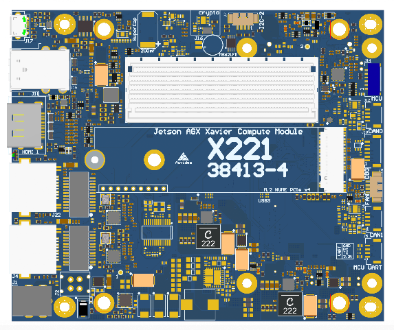
<table><thead><tr><th width="110.33333333333331"></th><th>Top side</th><th>Bottom side</th></tr></thead><tbody><tr><td><p>X221</p><p>(Rev 4)</p></td><td><img src="https://22655135-files.gitbook.io/~/files/v0/b/gitbook-x-prod.appspot.com/o/spaces%2FcUvqgsEqIqoso9khJDrs%2Fuploads%2FVVMYjcaK9Y4kJ5uaQX4L%2F1.png?alt=media" alt="A screenshot of a computer

Description automatically generated with medium confidence" data-size="original"></td><td>\<img src="/files/wBt5N8pF8fFG8gOh6u6e" alt="A screenshot of a computer

Description automatically generated with medium confidence" data-size="original"></td></tr><tr><td><p>X221-AI</p><p>(Rev 4)</p></td><td>\<img src="/files/U7X4qppuEXvQVdszR6rU" alt="A screenshot of a computer

Description automatically generated with medium confidence" data-size="original"></td><td>\<img src="/files/m6I0EyMsgAYkGGbT50Ho" alt="A screenshot of a computer

Description automatically generated with medium confidence" data-size="original"></td></tr></tbody></table>

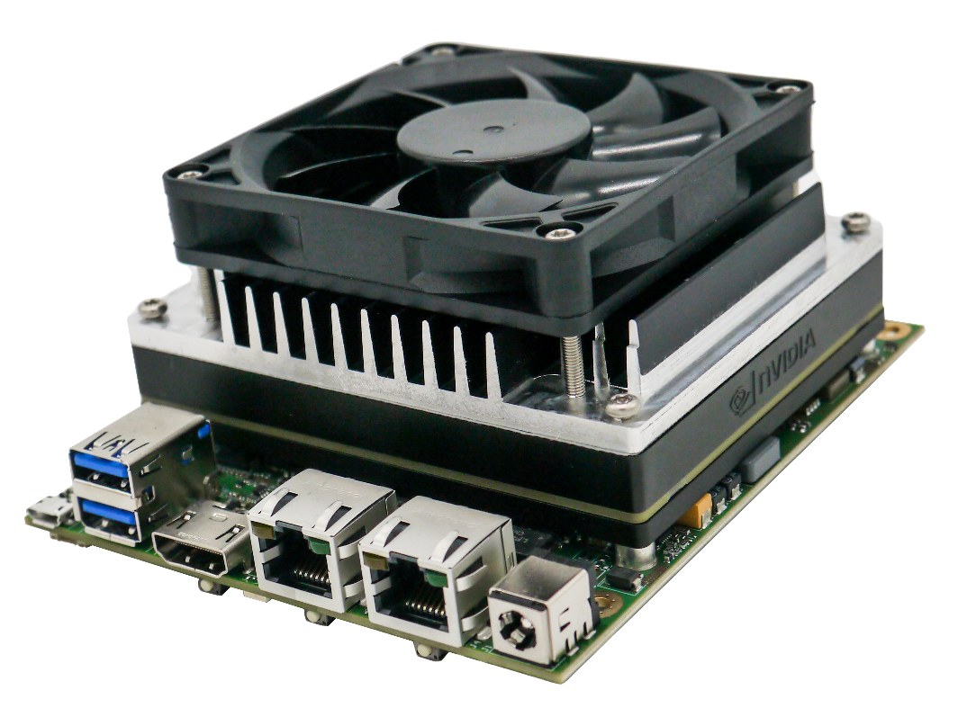
<figure><img src="https://22655135-files.gitbook.io/~/files/v0/b/gitbook-x-prod.appspot.com/o/spaces%2FcUvqgsEqIqoso9khJDrs%2Fuploads%2F5fDeh5JVxKqizsP8X4U3%2F5.png?alt=media" alt=""><figcaption><p>The picture shows a prototype custom heatsink, designed for the AGX Xavier. It is designed to mount a standard 80x80mm fan.</p></figcaption></figure>

## Power consumption <a href="#toc105600614" id="toc105600614"></a>

<table><thead><tr><th width="242">Description</th><th width="131">X221-LC R2</th><th width="121">X221-AI R2</th><th width="106">X221 R4</th><th>X221-AI R4</th></tr></thead><tbody><tr><td>Carrier board logic</td><td>1-2W</td><td>1-2W</td><td>1-2W</td><td>1-2W</td></tr><tr><td>1.8/3.3/5V power converter efficiency</td><td>>90%</td><td>>90%</td><td>>90%</td><td>>90%</td></tr><tr><td>Power in converter efficiency</td><td>-</td><td>>90%</td><td>-</td><td>>90%</td></tr></tbody></table>

If you intend to use MAXN mode, the LC version is better suited because it does not have a power limiting input converter. The full version features a high voltage power in converter with an output of 12V 5A, so that a maximum power setting of 30W is recommended.

It is possible to bypass the power input converter by moving two 0805 beads, as seen in the picture below. With this patch, the input voltage is limited to 12V as the power input converter is bypassed.

![](https://22655135-files.gitbook.io/~/files/v0/b/gitbook-x-prod.appspot.com/o/spaces%2FcUvqgsEqIqoso9khJDrs%2Fuploads%2FaubWjczroCklxV2UFh99%2F6.png?alt=media)